
1. System Connection Procedure
Step 1: Software Configuration
Connect projector to PC via USB Type-B cable
Launch proprietary configuration software (download from Optical Prisms and Sensors and Modules Manufacturer | SICUBE (si-cube.com))
Set parameters:
UV intensity: 0-100mW/cm² (adjustable)
Step 2: Power Supply Integration
Verify voltage compatibility (12-24V DC ±10%)
Connect power cable to:
Projector input: 3-pin XLR (male)
Printer PDB: 24V terminal block
Current requirement: 6A sustained / 8A peak
Step 3: Video Interface Setup
Use provided HDMI 2.1 cable (1m length)
Connection path:
Projector HDMI IN (Type A female)
Control board HDMI OUT (19-pin)
Step 4: Control Protocol Link
Connect USB-C to printer's host port
Protocol specifications:
Baud rate: 115200
Command set: MODBUS RTU
2. Calibration Process
Step 5: Optical Alignment
Power on system (warm-up time: 90s)
Place calibration paper at build plate
Rotate focus ring (±15° adjustment range)
Verify sharpness with test pattern
Step 6: Print Initialization
Load print file (.photon format)
Confirm resin tray installation
Start sequence:
UV shutter open
Layer projection begins
Z-axis movement initiated
3. Safety Indicators
✔ Green LED: Normal operation
⚠ Yellow LED: Cooling active
✖ Red LED: Fault condition
4. Compliance Standards
CE EN 62471:2008 (UV safety)
FCC Part 15B (EMC)
RoHS 3 (2015/863/EU)
Share:
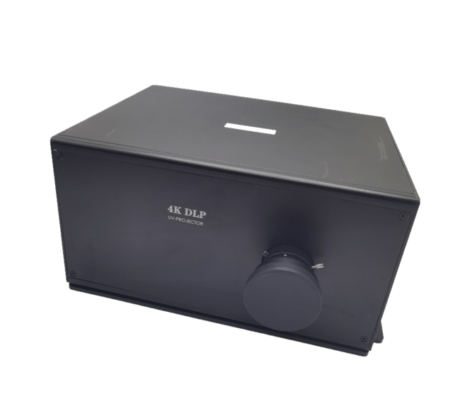
UV DLP Projector Integration Manual for Industrial-Grade 3D Printing Systems
Why Use a UV Projector for DLP 3D Printing?
43 コメント
ubm51y
fo99mq
0040hr
0v7bwb
kjpbbv